

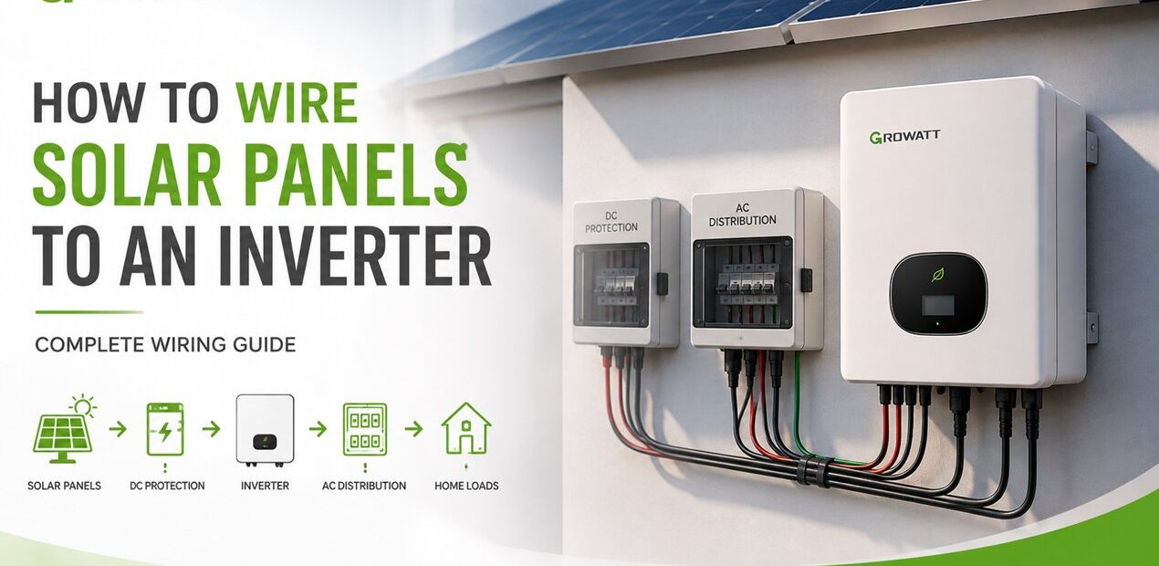
Wiring solar panels to inverter is not simply a matter of joining a few cables. The number of panels, their voltage, the inverter’s MPPT range, and the way the panels are arranged all affect the final connection.
In most systems, solar panels are wired in series, parallel, or a combination of both before they are connected to the inverter’s PV input. The right configuration depends on the electrical specifications of the panels and inverter.
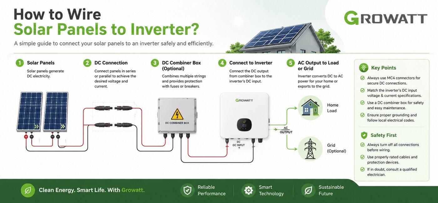
How to Wire Solar Panels to an Inverter Step by Step
Step 1: Check the Inverter Specifications
Start with the inverter, not the cables.
Find these values in the datasheet or installation manual:
- Maximum PV voltage
- MPPT voltage range
- Maximum input current per MPPT
- Number of MPPT inputs
- Maximum PV power
- Required connector type
These values determine how the solar panels can be arranged.
Step 2: Check the Solar Panel Specifications
Look at the panel datasheet and identify:
Voc, Vmp, Isc, Imp, and maximum power.
Do not use only the wattage when designing the string.
Two 500 W panels can have different voltage and current characteristics, and that difference matters when they are connected to an inverter.
Step 3: Decide on Series or Parallel Wiring
Use the panel and inverter specifications to determine the string configuration.
For a series string, make sure the combined Voc remains below the inverter’s maximum PV voltage.
| Wiring Method | Voltage | Current | Main Advantage | Main Consideration |
|---|---|---|---|---|
| Series | Increases | Approximately unchanged | Higher string voltage | Maximum PV voltage |
| Parallel | Approximately unchanged | Increases | Higher current | MPPT current limit |
| Series + Parallel | Increases | Increases | Flexible system sizing | Both voltage and current limits |
For parallel strings, make sure the combined current does not exceed the inverter’s maximum input current.
If the inverter has several MPPT trackers, the strings may also be distributed between different MPPT inputs.
Step 4: Connect the Solar Panels
For a series string, connect:
Panel 1 (+) → Panel 2 (-)
Then continue the same pattern until the required number of modules is connected.
The unused positive and negative terminals at the two ends of the string become the PV output.
For parallel strings, the corresponding positive and negative conductors are combined using suitable connectors or equipment designed for the application.
Do not mix up positive and negative polarity.
Step 5: Install the Required DC Protection
Depending on the system design and local electrical requirements, the PV circuit may include:
- DC isolator
- PV-rated fuses
- DC circuit breaker
- Surge protection device
- Grounding/earthing equipment
Protection devices must be rated for DC photovoltaic circuits. An AC-rated component is not automatically suitable for a PV DC circuit.
Step 6: Connect the PV Strings to the Inverter
Once the string configuration and polarity have been checked, the PV cables can be connected to the appropriate MPPT inputs on the inverter.
If the inverter has multiple MPPT trackers, follow the manufacturer’s recommended arrangement.
This is also the stage where connector compatibility matters. Use compatible PV connectors and avoid mixing connector types simply because they physically appear to fit.
Step 7: Connect the Inverter to the Rest of the System
The next connection depends on the type of solar installation.
An on-grid system normally follows:
PV Array → Inverter → AC Protection → Main Distribution Board → Grid
An off-grid system typically follows:
PV Array → Inverter → Battery / Loads
A hybrid system can combine:
PV Array → Hybrid Inverter → Battery + Loads + Grid
The exact wiring varies by inverter model, so the manufacturer’s connection diagram should always take priority.
Solar Inverter Wiring for On-Grid, Off-Grid and Hybrid Systems
The PV side may look similar across different systems, but the rest of the wiring can be quite different.
| System Type | PV Input | Battery | Grid | Typical Power Flow |
|---|---|---|---|---|
| On-Grid | Yes | Usually no | Yes | PV → Inverter → Loads/Grid |
| Off-Grid | Yes | Yes | Usually no | PV → Inverter → Battery/Loads |
| Hybrid | Yes | Yes | Yes | PV → Battery/Loads/Grid |
On-Grid Inverter Wiring
A grid-tied inverter converts DC power from the solar array into AC electricity that can be used by local loads or exported to the electrical grid, depending on the system configuration and local regulations.
The basic arrangement is:
Solar Panels → DC Protection → Inverter → AC Protection → Distribution Board
For larger commercial installations, the inverter and protection equipment must be selected according to the system voltage, current and power requirements. For example, when evaluating an On grid 15 kw inverter, the PV string configuration should be calculated from that particular inverter’s MPPT range and maximum DC input specifications rather than from its 15 kW AC rating alone.
Off-Grid Inverter Wiring
An off-grid system does not rely on the utility grid as its primary power source. The inverter works with a battery bank to provide energy when solar production is insufficient.
A simplified connection looks like:
Solar Panels → MPPT → Inverter → Loads
with:
Battery ↔ Inverter
Battery wiring has its own voltage, current and protection requirements. The battery bank should not be designed simply by matching its nominal voltage to the inverter without checking the manufacturer’s specifications.
If you are comparing equipment for an off-grid setup, the Growatt off grid inverter (گرووات)range is an example of inverter equipment designed for systems where battery storage plays a central role.
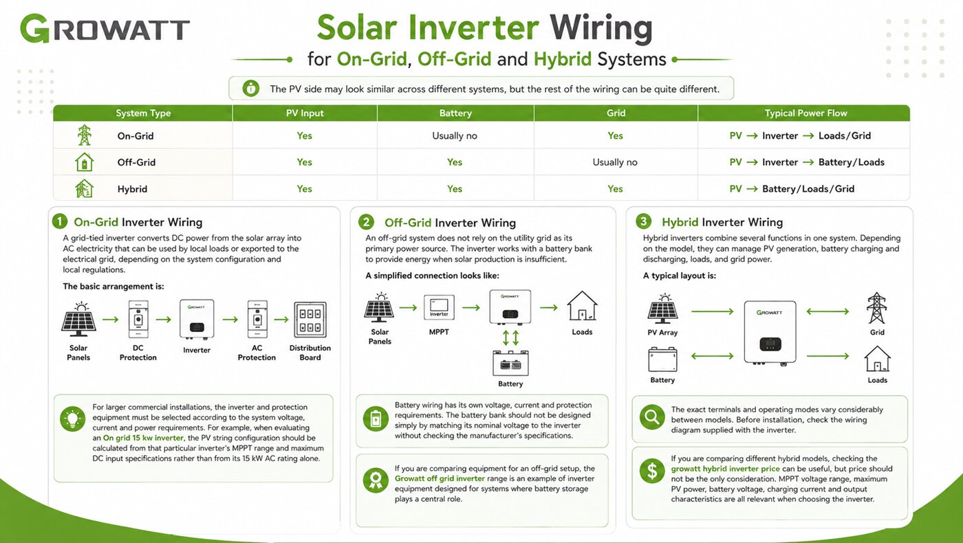
Hybrid Inverter Wiring
Hybrid inverters combine several functions in one system. Depending on the model, they can manage PV generation, battery charging and discharging, loads, and grid power.
A typical layout is:
PV Array → Hybrid Inverter
Battery ↔ Hybrid Inverter
Grid ↔ Hybrid Inverter
Loads ↔ Hybrid Inverter
The exact terminals and operating modes vary considerably between models. Before installation, check the wiring diagram supplied with the inverter.
If you are comparing different hybrid models, checking the growatt hybrid inverter price can be useful, but price should not be the only consideration. MPPT voltage range, maximum PV power, battery voltage, charging current and output characteristics are all relevant when choosing the inverter.
Solar panel and inverter wiring diagram

A solar inverter wiring diagram is among the crucial tools for understanding how to properly connect all the components of a solar power system. It shows the specific connections between the solar panels, the inverter, and the main electrical panel. The diagram typically includes the layout of the solar panels on the roof, the wiring from the panels to the inverter, and the wiring from the solar inverter to the main electrical panel. It also indicates the proper grounding and safety measures that need to be taken during installation.
Proper wiring of a solar inverter is essential for the efficient and safe operation of a solar power system. The diagram is used by solar installers to ensure that the energy system is correctly wired and connected according to the manufacturer’s guidelines. This includes verifying that the correct wire sizes and fuses are used, as well as ensuring that all solar inverter connection diagrams are secure and insulated. Failure to follow the wiring diagram can result in system malfunctions, reduced efficiency, or even electrical hazards.
Having a detailed solar inverter wiring diagram also makes troubleshooting and maintenance easier. If there are ever issues with the system, having a clear diagram to reference can help identify potential sources of the problem and facilitate a quick resolution. Additionally, having a well-documented wiring diagram can be beneficial for future upgrades or modifications to the solar power system, as it provides a clear roadmap for making changes to the system.
Where can I find the solar panel and inverter wiring diagram?
You can find solar panel and solar inverter wiring diagrams in a variety of places, both online and offline. One option is to visit the websites of solar panel manufacturers or retailers, as they often provide detailed wiring diagrams and instructions for installing their products. These diagrams can help you understand how to connect your solar panels and inverters to your electrical system in a safe and efficient manner.
If you prefer a more hands-on approach, many books on solar power systems include detailed diagrams and step-by-step instructions for setting up your solar panels and inverters. These resources can be especially helpful for those who prefer to have a physical reference guide while working on their solar installation.
Additionally, online forums and websites dedicated to solar power and renewable energy are great sources of information and advice for DIY solar installers. Many of these online resources offer free access to wiring diagrams, installation tips, and troubleshooting guides from experienced professionals.
High quality growatt inverter seller
Overall, solar inverter wiring plays a critical role in the functionality and reliability of a solar energy system. Properly installed wiring ensures that the system operates safely and efficiently, maximizing the amount of solar energy converted into usable electricity. By following industry best practices and guidelines, solar installers can help you make sure that the wiring is done correctly, ultimately leading to a successful and long-lasting solar energy system. To buy Growatt solar inverter in the UAE, check our site and call our expert to guide you.
Frequently Asked Questions About Wiring Solar Panels to an Inverter
Solar panels are typically connected to an inverter through one or more PV strings. The panels can be wired in series, parallel, or a combination of both, depending on the inverter's MPPT voltage range, maximum PV voltage, input current, and the electrical characteristics of the panels. The PV strings are then connected to the appropriate MPPT input through the required DC protection and isolation equipment.
Solar panels can be connected in either series or parallel, depending on the system design. Series wiring increases the total PV voltage while keeping the current approximately the same, whereas parallel wiring keeps the voltage similar and increases the available current. The correct configuration should be selected according to the inverter's MPPT voltage and maximum input current.
The number of solar panels that can be connected to an inverter depends on the panel's voltage, current, power rating, and the inverter's maximum PV voltage, MPPT operating range, maximum input current, and maximum PV power. The number should be calculated from these electrical specifications rather than determined only by the inverter's rated output power.
When solar panels are connected in series, the voltage of each panel is added together while the current remains approximately the same as the current of one panel. This configuration is commonly used to reach the voltage required by the inverter's MPPT range. The total string voltage must remain below the inverter's maximum PV input voltage.
When solar panels or PV strings are connected in parallel, their positive terminals are combined and their negative terminals are combined. The voltage remains approximately the same while the available current increases. The combined current must stay within the maximum input current allowed by the inverter or MPPT.
For panels connected in series, the approximate string voltage can be calculated by multiplying the panel voltage by the number of panels. For example, four panels with a Vmp of 40 volts would have an operating string voltage of approximately 160 volts. The total Voc must also be checked, especially at low temperatures, to ensure that the inverter's maximum PV voltage is not exceeded.
MPPT stands for Maximum Power Point Tracking. It allows the inverter to operate the PV array around its maximum power point as operating conditions change. When designing solar panel wiring, the string voltage should remain within the inverter's specified MPPT operating range, while the input current must also remain within the MPPT's maximum limit.
Solar PV systems normally use dedicated photovoltaic DC cable designed for outdoor installation and exposure to sunlight, temperature changes, and moisture. The appropriate conductor size depends on factors such as current, cable length, allowable voltage drop, installation conditions, temperature, and applicable electrical requirements.
The required DC protection depends on the PV array design, number of parallel strings, equipment specifications, and applicable electrical requirements. Where protection is required, the devices should be specifically rated for the DC voltage and current of the photovoltaic system. A standard AC-rated protection device should not automatically be assumed to be suitable for a PV DC circuit.
Solar panels can be connected directly to an inverter when the inverter is specifically designed to accept PV input and the electrical characteristics of the solar array are within its permitted limits. Before making the connection, check the inverter's maximum PV voltage, MPPT voltage range, maximum input current, and maximum PV power.
Before connecting a PV array, check the solar panel Voc, Vmp, Isc, Imp, and power rating, then compare these values with the inverter's maximum PV voltage, MPPT operating range, maximum input current, and maximum PV power. Polarity, cable size, connector compatibility, grounding, and required DC protection should also be verified before commissioning the system.
Different solar panels may be connected to the same inverter in some system designs, but panels with significantly different electrical characteristics should not be mixed in the same string without careful design. Differences in voltage, current, power, and temperature characteristics can affect string performance. Matching modules with similar electrical characteristics is generally preferable.
An on-grid system normally connects the PV array to the inverter and then to the AC distribution system and utility grid. An off-grid system typically connects the inverter to a battery bank and electrical loads without relying on the utility grid. A hybrid system can combine solar panels, batteries, loads, and the utility grid, with the exact wiring depending on the inverter model.
A generic solar inverter wiring diagram can help explain how the main components are connected, but it should not replace the wiring diagram supplied for the specific inverter model. Terminal locations, MPPT inputs, battery connections, protection requirements, and operating limits can differ between models, so the manufacturer's installation manual should be followed for the actual installation.
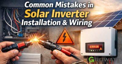
Common solar panel wiring mistakes include exceeding the inverter's maximum PV voltage, exceeding the MPPT input current, reversing DC polarity, using incorrectly sized cables, installing unsuitable protection devices, mixing mismatched panels, using incompatible connectors, and ignoring temperature effects on PV voltage. The PV string should be checked against the inverter specifications before it is connected.
Solar panels can produce hazardous DC voltage whenever they are exposed to sunlight, so wiring should not be treated as a simple DIY electrical task. The installation should follow the inverter manufacturer's instructions, applicable electrical regulations, and required isolation and protection procedures. A qualified solar installer or electrician should handle the physical installation and commissioning when required. How do you wire solar panels to an inverter?
Should solar panels be connected in series or parallel?
How many solar panels can I connect to one inverter?
What happens when solar panels are connected in series?
What happens when solar panels are connected in parallel?
How do I calculate the voltage of a solar panel string?
What is MPPT and why does it matter for solar panel wiring?
What cable is used to connect solar panels to an inverter?
Do solar panels need a fuse or circuit breaker before the inverter?
Can solar panels be connected directly to an inverter?
What should I check before connecting solar panels to an inverter?
Can different solar panels be connected to the same inverter?
What is the difference between on-grid, off-grid, and hybrid inverter wiring?
Can I use a generic solar inverter wiring diagram for installation?
What are the most common solar panel wiring mistakes?
Is it safe to wire solar panels to an inverter yourself?




3 thoughts on “How to Wire Solar Panels to an Inverter: Complete Wiring Guide”
Give me the full map of soled installation.
I wants to be an installer.
سلام میشود تمام بخش ویرنگ این اینورتر ها را برم ارسال کنی